-40%
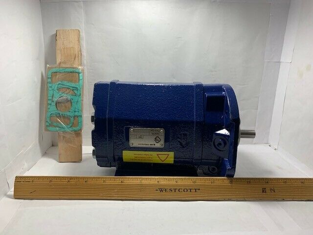
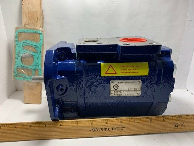
PUMP ONLY ACE TYPE 032 N3 NVBP no. IOW032N2001
$ 1053.35
- Description
- Size Guide
Description
1. Applications1.1 Functionality
The Std Line (standard) ACE pump comes in two executions; Lube Line and Fuel Line. The main difference is the shaft seal design; (V-Seal) - optimized for light duty and (T-Seal) - heavy duty respectively.
The ACE pump is used for a number of different fluids:
Lubrication oil, fuel oil, vegetable oil, hydraulic oil and other hydraulic fluids, polymers, emulsions and any non-aggressive fluid with sufficient lubricating properties.
If requested, the ACE pump may be certified according to any of following classification societies: DNV, BV, LRS, ABS, RS, GL, RINA, KR, NK, RMR or CCS.
1.2 Applications
Typical applications are:
- Lubrication of diesel engines, gears, gas and steam turbines, hydro turbines and paper machines
- Circulation for cooling and filtration in large machineries, hydraulic systems and transformer oil for insulation in transformers
- As transfer pumps onboard vessels, in power plants, oil factories, refineries, tank farms etc
- Fuel supply duties for engines
- Supply and circulation of fuel oil
1.3 Installation
The pump is designed to be flange-mounted to its electric motor via a connecting frame and a flexible shaft coupling. By the angle bracket, the pump may be mounted horizontally or vertically.
The ACE pump can also be mounted on valve blocks called T4 or T5.
As standard, the pump is delivered including counter flanges (IMO AB design).
For more information about installation, see Installation and Start-up instruction for low pressure pumps.
3. Technical Data
3.1 Pressure Information
Pressure relief valve The pump is equipped with an integral pressure relief valve with internal return, limiting the differential pressure across the pump and protecting the pump. Should the discharge line be blocked, the relief valve will open by the pressure.
The valve is adjustable for different opening pressures. The value of the pressure limit can be set at the factory and should be adjusted at installation (see Installation & Start-up instruction for low-pressure pumps).
The maximum pressure accumulation varies with pump size, speed and viscosity, but will normally not exceed 4 bar.
The valve has a maximum set pressure of 16 bar.
Inlet pressure
Minimum inlet pressure (suction capability) is dependent on fluid viscosity and rotation speed. It increases with decreasing viscosity and decreasing speed. Information about minimum inlet pressure for each individual duty case can be obtained from IMO AB or pump selection software WinPump.
Maximum inlet pressure is 7 bar.
Discharge pressure
Maximum discharge pressure is 16 bar.
Differential pressure
Maximum differential pressure is 16 bar but reduced at low viscosities according to table below
Viscosity [cSt]
1,4
2
6
10
>12
Max. diff. pressure [bar]
6,9
8
12,4 15
16
Refer to your IMO representative or use the pump selection software WinPump to determine the exact operating limits.
3.2 Driver information
Driver type
The pump is designed to be connected to an electrical motor via a flexible shaft coupling.
Speed
The maximum speed is 3600 rpm. For higher speeds, contact IMO AB.
Rotation
The pump is designed to operate in one rotational direction only, as standard clockwise when facing the shaft end. Pumps for CCW operation can be delivered on special request. For shorter periods of time, a few minutes for emptying a discharge line, the pump may be operated in reverse direction, provided the back pressure is limited to 3 bar
3. Technical Data
3.3 Sound level
Typical pump sound levels refer to free field conditions at a distance of 1 m from the pump. Noise of driver excluded in the quoted figures. The sound levels are measured at a discharge pressure of 5 bar, speed 2940 rpm and viscosity 40 cSt, according to ISO-3741.
Size
025
032
038
Sound level dB [A]
58
58
58
3.4 Moment of Inertia
Moment of intertia [10-6 kgm2]
Size
025
032
038
Value
49
72
194
3.5 Fluid viscosity
Lube Line seal (Seal version code V):
1,4 – 800 cSt for Lube and hydraulic oil
Fuel Line seal (Seal version code T):
1,4 – 3500 cSt for Fuel oil
For higher viscosity, contact IMO AB.
3.6 Fluid temperature
Lube Line (Seal version code V): -20 – +90 °C
Fuel Line (Seal version code T): -20 – +155 °C
4. Design
4.1 Ball bearing
The pump is fitted with an internal ball bearing which continously is being greased by the handling media.
4.2 Design material
Model
Material pump
Material rotor
Material idler
Material seal
Material Elastomers
ACE NV Nodular cast iron Steel, surface treated Cast iron, surface treated
Carbon/Silicon carbide Viton
ACE NT Nodular cast iron Steel, surface treated Cast iron, surface treated Silicon carbide / Silicon Viton
carbide
5. Performance
Typical performance values at 5 bar
Flow calculated at 26 cSt, power at 260 cSt
025L
025N
rpm
l/min
kW
l/min
kW
1470
10,0
0,3
13,5
0,4
1770
12,9
0,4
17,7
0,5
2950
24,5
0,9
34,1
1,0
3550
30,4
1,1
42,5
1,3
032L
032N
rpm
l/min
kW
l/min
kW
1470
22,8
0,5
35,9
0,8
1770
29,0
0,7
44,6
1,0
2950
53,3
1,3
79,0
1,9
3550
65,6
1,7
96,4
2,4
038K
038N
038D
rpm
l/min
kW
l/min
kW
l/min
kW
1470
45,5
1,0
55,8
1,3
59,1
1,2
1770
57,1
1,3
70,5
1,7
76,2
1,5
2950
102,9
2,5
128,4
3,2
143,9
2,9
3550
126,2
3,2
157,9
4,1
178,2
3,6
